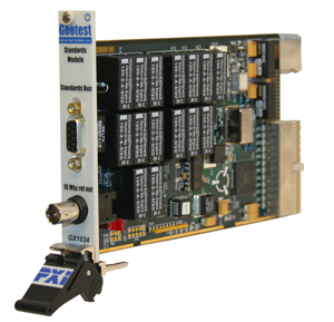
The GX1034 offers PXI system designers the capability to develop a system re-certification strategy that employs only internal system resources. By incorporating the GX1034 as part of a system configuration, it is possible to develop a system accuracy verification strategy that can recertify a system’s source and measure baseband instrumentation – resulting in simplified support / maintenance logistics and improved system availability.
The GX1034’s standards exhibit excellent long term stability with absolute accuracy achieved by employing an on-board EEROM, which contains NIST traceable calibration values for source and resistor standards. The module also includes source and measure resources which can be used to support system self-test functions including continuity verification and verification of instrument functionality.
The GX1034 provides a DC voltage source reference, an AC voltage source reference, 8 low drift resistor references, and a precision 10 MHz frequency reference. The DC and AC sources supply up to ±9 V and include a 3 decade resistive divider network for attenuation of the output level. The resistor references include four- wire 1, 10 and 100 Ω resistors and two-wire 1 K, 10 K, 100 K, 1 M and 10 MΩ resistor values. The 10 MHz frequency reference employs a high stability, oven controlled crystal oscillator which can also provide lower frequencies via a 24-bit divider. Both the 10 MHz output and the divider output can drive 50 Ω loads. In addition, when the module is installed in slot 2 of a PXI chassis, it can be the PXI 10 MHz backplane clock source.
Additional features include a 0 - 20 mA current source; a 16-bit A to D for measuring voltages up to ±10 V, and on-board monitoring of the card’s ambient operating temperature. The card also includes a signal multiplexer which provides the ability to connect two and four wire resources to the card’s output connector. All voltage resources, resistor standards, clock divider outputs, and A to D inputs are isolated and floating from the PXI bus, ensuring a low noise environment and minimizing the possibility of ground loops which can affect overall accuracy and performance.
The board is supplied with a 32-bit DLL driver. Various interface files provide access to the DLL from programming tools and languages such as ATEasy, LabVIEW, C/C++, Microsoft Visual Basic®, Delphi, and more. The available virtual panel can be used to interactively adjust and control the instrument from a window that displays the current instrument settings and measurements. An On-Line help file and PDF User's Guide provides documentation that includes instructions for installing, using and programming the board.